|
| Modeling using cross sections The following is a tutorial of modeling using cross sections. 以下は断面を使ったモデリングの例です。 Step 1 The following is an example of Modeling using cross sections. In this example, the subject is SF space fighter in Fig.1. 断面を使ったモデリングの例として、Fig.1 のようなSF風宇宙戦闘機を作ってみましょう。
The center body of this fighter will be made by modeling using sections indicated in red line in Fig.2. Engine pods placed in each side of the fighter will be made from some primitives such as cube or cylinder. Fig.2 の赤い線で示したような断面を考えて、この戦闘機の中央の胴体をモデリングします。左右のエンジンの部分は円柱や立方体などのプリミティブから作成することにします。 Step 2 This example shows a method arranging sections along "Frame". "Frame" is a guide for arranging sections. First, make "Frame" used as guide for arranging cross sections. 今回は、断面を作って並べていくときにそのガイドとなるような「型枠」使う手法を紹介します。 まずはじめに、断面を並べるときにガイドとなる「型枠」から作成します。
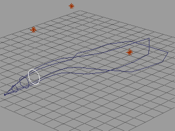
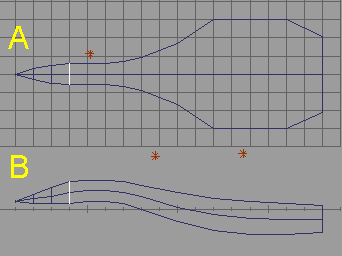
Make an outline of side view of center body roughly using polygon tool shown in Fig3-A. After this, arrange outline using point editing tool as shown Fig.3-B. In this time, arrange vertices along cyan arrow in Fig.3-B. This will be useful for arranging sections along this outline. The length of (1) is a distance of each section. Take this distance smaller in the point that the change of outline is large. Take this distance larger in the point that the change of outline is small. Make an outline of top view of center body. First, make a polygon roughly shown as Fig.4-A. Next, arrange the polygon shown as Fig.4-B. 胴体の側面から見た輪郭を作成します。多角形ツールでおおまかな形をFig.3のAのように作成します。その後、Fig.3のBのように頂点編集ツールで形を整えます。その際、あとで断面を並べやすいように、水色の矢印で示されるように上下の頂点をそろえて配置します。正確に配置するためには、グリッドや数値入力を活用します。また、後で断面同士の間隔になる(1)の長さは、輪郭の形状の変化が大きいところでは小さくとり、輪郭の形状の変化が小さいところでは大きくとります。 同様に、上面から見た輪郭を作成します。Fig.4のAのように大まかに作成し、Fig.4のBのように形状を整えます。このとき、あとで適切に断面を並べられるように、側面から見た輪郭と照らし合わせながら各頂点を配置します。 Step 3 Assemble two outlines to make "Frame" as shown in Fig.5-A. In this time, this Frame is useless because forward parts of each outline are separate. Bend outline of top view by point editing tool shown as Fig.5-B to make the Frame correct. 次に、2つの輪郭を図のAのように組み合わせます。このままでは正しく「型枠」として使えないので、図のBのように、上面から見た輪郭を頂点編集で曲げて、側面から見た輪郭にあわせます。
Step 4 Make 16-sided polygons and place them as inscribed circles of the Frame shown in Fig.6-1, Fig.6-2-A, and Fig6-2-B. In this time, you may be required that transforming these 16-Sided polygons to fit to the Frame. I recommend that when you make next 16-Sided polygon, make this from already placed 16-Sided polygon by copy. 正多角形ツールで16角形を作成し、それを型枠に内接するように変形させながら配置していきます。(Fig.6-1) その際、図6-2-A、6-2-Bのように側面及び平面で見て正しく内接するように調節します。新しい16角形を作成するときは、すでに配置されたもののコピーを作成してそれを使用することをお勧めします。
|


